 Official Stores
Best Deals on Genuine Manufacture's Official Brands Stores | SolarShop Africa
Solar Panels
Jinko Solar
JA Solar
Trina Solar
Longi Solar
RenePV
Yingli Solar
Amerisolar
Suntech
Canadian Solar
AfricelSolar Inverters
Solar Water Heaters
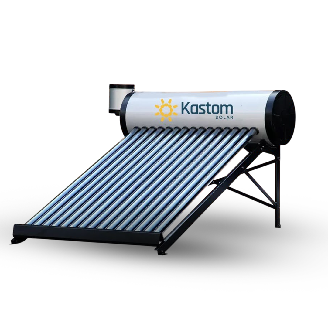
Kastom Solar
Megasun Solar
Dayliff Ultrasun
Seven SS Stars
Yogisun Solar
Chromagen
Eraslan
Twiga Solar
Termicoil
KodsunSolar Pumping Inverters
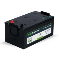
Lithium ion Batteries
BYD
Weco
Lithium Valley
Megatank
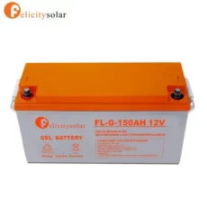
Felicity
Kastom Solar
Vestwood
SRNE
Zetara
KijoSolar Outdoor Lights
MODI | OPTONICA
Vellmax
AllTop
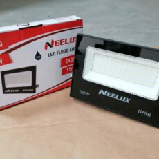
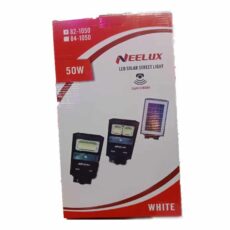
Neelux
TNTorch
Twiga
DP Light
Solar Light
Blue Carbon
LuxmanBuy at SolarShop at the Best Price, support & Genuine warrany. Glean Energy is Now
 Solar Panels
Best Deals on Solar Panels in Kenya | SolarShop Africa
Solar Panels By Technologies
Monocrystalline
Polycrystalline
MonoFacial
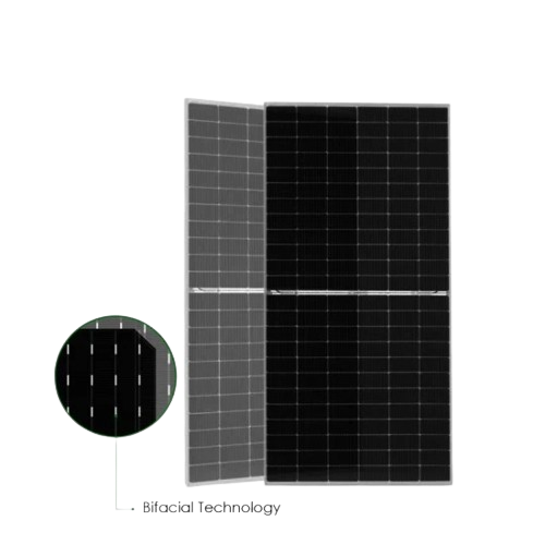
Bifacial
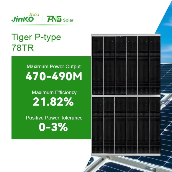
P-Type
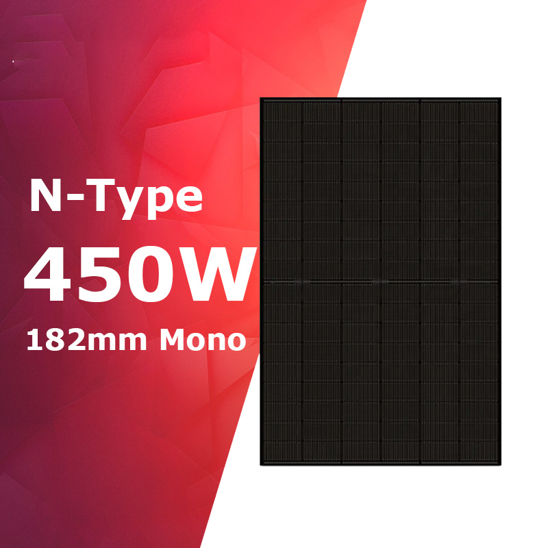
N-Type
Armophous Black
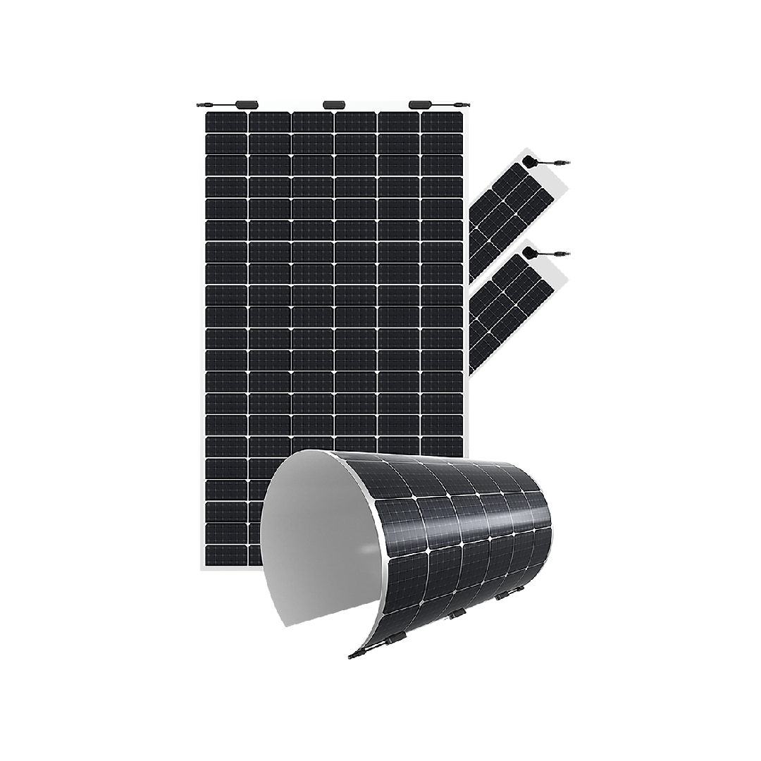
Fexible Panels
Frameless
Building IntegratedSolar Panels By Brands
Jinko Solar
JA Solar
Trina Solar
Longi Solar
RenePV
Yingli Solar
Amerisolar
Suntech
Canadian Solar
Sunpact
Astro Energy
Wuxi Solar Solareon
Solinc
Africel
Chrolide Solar
Dayliff Solar
Powermax
SolarMax
SolarpexSolar Panels By Rating (Watts)
5 W to 100 W
105 W to 200 W
205 W to 300W
305 W to 400 W
405 W to 500 W
505 W to 600 W
605 W to 700 WBuy at SolarShop at the Best Price in Kenya. Genuine 25 Years Linear Warranty, 10 Years Defect Warranty.
 Solar Inverters
Best Deals on Solar Inverters in Kenya |SolarShop Africa
Solar Inverters By Technology
Offgrid Inverters
Hybrid Offgrid
Hybrid Ongrid
Ongrid | Grid Tie
Low Frequency
High Frequency
Inverter Chargers
Low Voltage
High Voltage
Simple Plug & PlayPremium Solar Inverter Brands
SMA
Victron Energy
Fronius
Outback
SolarEdge
Huawei Solar
Sungrow
Solis
GrundFos RSI
LorentzSolar Inverters By Rating (Watts)
Less than 1KVA
1000 KVA | 1Kw
1500 VA | 1.5 Kw
2000 VA | 2 Kw
3000 VA | 3 Kw
3500 VA | 3.5 Kw
5000 VA | 5 KW
6000 VA |6 Kw
8000 VA | 8 Kw
10000 VA | 10 Kw
12000 VA | 12Kw
12Kw to 100 KwEconomy Solar Inverter Brands
Deye
Jinko
GoodWe
TBB Power
Growatt
Must
Kastom Solar
Infini
INVERT
Hober
Veichi
INVTInverters By Application
Heavy Commercial 200Kw+
Medium Commercial 50Kw to 200Kw
Small Commercial 20Kw to 50 Kw
Residential and Offices
Electric Mobility Stations
Office Power Backups
Three Phase Power
Single Phase Power
Solar Water Pumping
Containerized SeriesBuy Solar Inverters at SolarShop at the Best Price in Kenya. Up to 5 Years on Selected Brands.
 Lithium-ion Batteries
Best Deals on Lithium Batteries in Kenya | SolarShop Africa
Premium Lithium Battery Brands
Tesla
Huawei
Weco
BYD
Jinko
ELFBULB
GoodWeEconomy Lithium Battery Brands
Kastom Solar
Megatank
Felicity Solar
Eastman
Growatt
KijoRetrofit Lithium Batteries By Rating (Capacity)
24 Wh| 6V | 4 Ah
60 Wh| 12V | 5 Ah
72 Wh| 12V | 6 Ah
144 Wh| 12 V | 12 Ah
216 Wh| 12 V | 18 Ah
312 Wh| 12 V | 26 Ah
420 Wh| 12 V | 35 Ah
480 Wh| 12 V | 40 Ah
1.2 KWh| 12 V | 100 Ah
2.4 KWh| 12 V | 200 AhLithium Batteries By Application
Rack mount Series
Wall Mount Series
High Voltage Series
Low Voltage Series
On Wheel SeriesProfessional Lithium Batteries By Rating
5.0 KWh| 24V | 200 Ah
4.8 KWh| 48V |100 Ah
5.12 KWh| 51.2 V | 100 Ah
7.2 KWh| 48 V | 150 Ah
10 KWh | 48V | 200 Ah
12.5 KWh | 48V | 250 Ah
15 KWh | 48V | 300 AhBuy Solar Solar Lithium Batteries at SolarShop at the Best Price in Kenya. Up to 5 Years Warranty on Selected Brands.
 Solar Batteries
Best Deals on Solar Batteries in Kenya | SolarShop Africa
Premium Solar Battery Brands
Rolls
BAE
Trojan
Sunlight
Eastman
Ceil
ChampionEconomy Battery Brands
Ritar
Prostar
Amizar
Renergy
Kratos
Future Energy
ALLGRAND
Weida
Gaston
SolarMAxRetrofit Lithium Batteries By Rating (Capacity)
24 Wh| 6V | 4 Ah
60 Wh| 12V | 5 Ah
72 Wh| 12V | 6 Ah
144 Wh| 12 V | 12 Ah
216 Wh| 12 V | 18 Ah
312 Wh| 12 V | 26 Ah
420 Wh| 12 V | 35 Ah
480 Wh| 12 V | 40 Ah
1.2 KWh| 12 V | 100 Ah
2.4 KWh| 12 V | 200 AhProfessional Lithium Batteries By Rating
5.0 KWh| 24V | 200 Ah
4.8 KWh| 48V |100 Ah
5.12 KWh| 51.2 V | 100 Ah
7.2 KWh| 48 V | 150 Ah
10 KWh | 48V | 200 Ah
12.5 KWh | 48V | 250 Ah
15 KWh | 48V | 300 AhBuy Solar Solar Batteries at SolarShop at the Best Price in Kenya. Up to 5 Years Warranty on Selected Brands.
 Inverter & Battery Combo
 Solar Water Heaters
Best Deals on Solar Water Heaters in Kenya |SolarShop Africa
Solar Water Heaters by Technology
Pressurized Heat Pipe
Non Pressurized E-Tubes
Pressurized Flat Plate Direct
Pressurized Flat Plate indirect
Pressurized Split system
Peressurized Vac-Rod
Swimming Pool Series
Heat-Pump SeriesSolar Water Heaters by Capacity
100 Liters
120 Liters
150 Liters
250 Liters
300 Liters
350 Liters
500 Liters
1000 Liters
1500 Liters
3000 LitersPremium Solar Water Heaters
Chromagen
Eraslan
Megasun
Ultrasun
Kodsun
Terasun
Solartek
TermcolEconomy Solar Water Heaters
Kastom Economy
Twiga Solar
Phoenix
Seven SS Stars
Sunrain
Supreme
AquaMax
Aquasun
Chloride Solar
HantiSolar Water Heaters by Application
Gravity Flow Systems
Pressurized Residential
For Salty Aggressive Water
For Swimming Pools
For Schools
For Hospitals
Split Tank systemBuy Solar Water Heaters at SolarShop at the Best Price in Kenya. Up to 5 Years on Selected Brands.
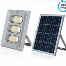
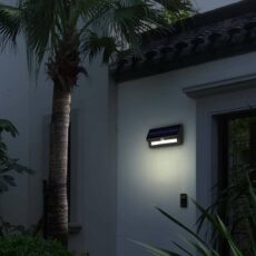
 Solar Outdoor Lights
Solar Outdoor Lighting
-
Select options
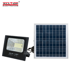
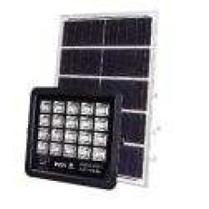
AllTop Solar Flood Lights – 150Watts | 250Watts
KSh9,125.00 – KSh13,500.00Price range: KSh9,125.00 through KSh13,500.00 -
Add to cart
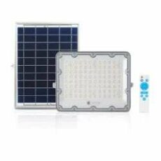
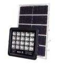
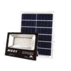
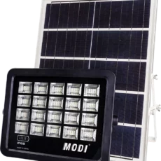
MODI 100 Watts LED Solar Flood Light MD-PT77 Series
KSh5,500.00Original price was: KSh5,500.00.KSh4,500.00Current price is: KSh4,500.00.
Free Shipping Within Nairobi and its Environs: 0.00 Ksh
 Solar Water Pumps
Free Shipping Within Nairobi and its Environs: 0.00 Ksh
 Solar Racking Systems
Free Shipping Within Nairobi and its Environs: 0.00 Ksh
 Solar Charge Controllers
Solar Charge Controllers
-
Add to cart
Must Solar Charge Controller 80 Amps 12v/24v/36v/48v 145VOC
KSh27,750.00Original price was: KSh27,750.00.KSh18,900.00Current price is: KSh18,900.00. -
Add to cart
Felicity 30Amps MPPT Solar Charge Controller | 12V/24V
KSh14,000.00Original price was: KSh14,000.00.KSh10,500.00Current price is: KSh10,500.00. -
Add to cart
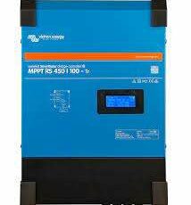
Victron Smart Solar MPPT 450/100-TR Charge Controller
KSh210,500.00Original price was: KSh210,500.00.KSh203,900.00Current price is: KSh203,900.00. -
Add to cart
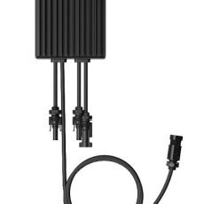
Huawei LUNA Power Module Controller
KSh148,900.00Original price was: KSh148,900.00.KSh143,900.00Current price is: KSh143,900.00. -
Add to cart
Victron Smart Solar MPPT 450/200-TR Charge Controller
KSh284,900.00Original price was: KSh284,900.00.KSh274,900.00Current price is: KSh274,900.00. -
Add to cart
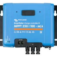
Victron Smart Solar MPPT 250/100 TR Charge Controller
KSh159,900.00Original price was: KSh159,900.00.KSh141,900.00Current price is: KSh141,900.00. -
Add to cart
Victron Smart Solar MPPT 150/100 TR Charge Controller
KSh138,900.00Original price was: KSh138,900.00.KSh124,900.00Current price is: KSh124,900.00. -
Add to cart
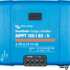
Victron Smart Solar MPPT 150/85 TR Charge Controller
KSh88,900.00Original price was: KSh88,900.00.KSh73,900.00Current price is: KSh73,900.00. -
Add to cart
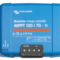
Victron Smart Solar MPPT 150/70 TR Charge Controller
KSh86,900.00Original price was: KSh86,900.00.KSh77,900.00Current price is: KSh77,900.00.
Free Shipping Within Nairobi and its Environs: 0.00 Ksh
-
 Solar Cables & Accessories
Cables & Accessories
Free Shipping Within Nairobi and its Environs: 0.00 Ksh
 Solar Water Heating Accessories
Free Shipping Within Nairobi and its Environs: 0.00 Ksh
 Other Solar Categories
Best Deals on Solar Panels in Kenya | SolarShop Africa
Solar Panels By Technologies
Monocrystalline
Polycrystalline
MonoFacial
Bifacial
P-Type
N-Type
Armophous Black
Fexible Panels
Frameless
Building IntegratedSolar Panels By Brands
Jinko Solar
JA Solar
Trina Solar
Longi Solar
RenePV
Yingli Solar
Amerisolar
Suntech
Canadian Solar
Sunpact
Astro Energy
Wuxi Solar Solareon
Solinc
Africel
Chrolide Solar
Dayliff Solar
Powermax
SolarMax
SolarpexSolar Panels By Rating (Watts)
5 W to 100 W
105 W to 200 W
205 W to 300W
305 W to 400 W
405 W to 500 W
505 W to 600 W
605 W to 700 WBuy at SolarShop at the Best Price in Kenya. Genuine 25 Years Linear Warranty, 10 Years Defect Warranty.
- Solar Panels
Best Deals on Genuine Manufacture's Official Brands Stores | SolarShop Africa

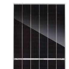
All Black Solar Panels
Buy at SolarShop at the Best Price, support & Genuine warrany. Glean Energy is Now
- Solar Inverters
Best Deals on Genuine Manufacture's Official Brands Stores | SolarShop Africa
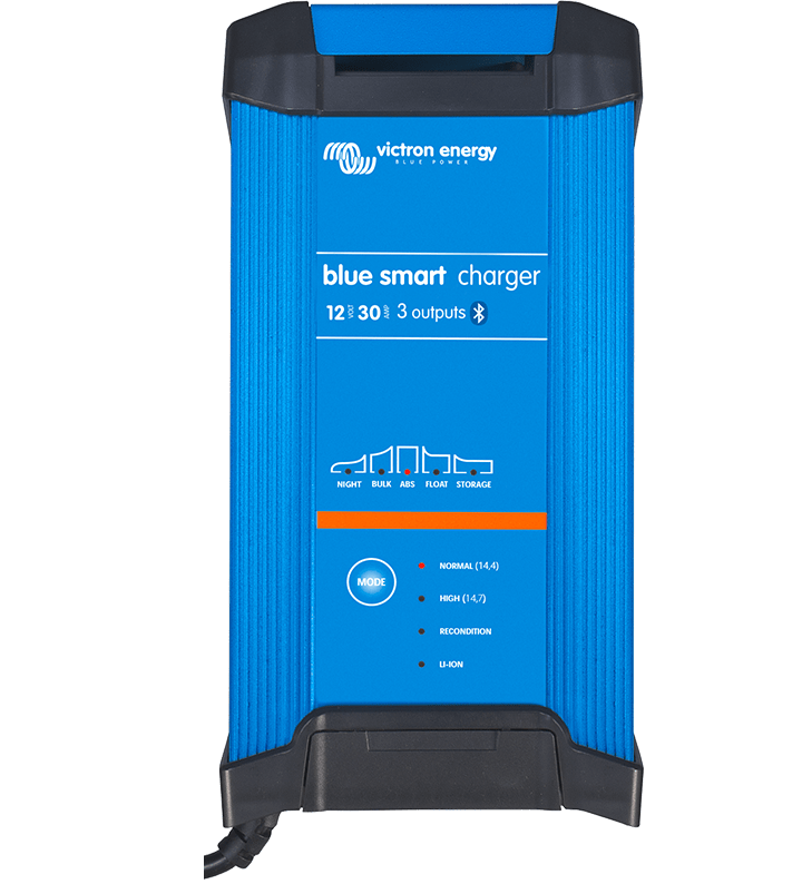
Offgrid Inverters
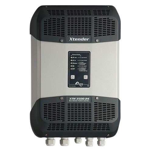
Inverter Chargers

Low Voltage Inverters

Hybrid Ongrid Inverters

High Voltage Inverters
Buy at SolarShop at the Best Price, support & Genuine warrany. Glean Energy is Now
- Solar Batteries
Best Deals on Genuine Manufacture's Official Brands Stores | SolarShop Africa

Battery Fuses

Plug & Play Inverters
Buy at SolarShop at the Best Price, support & Genuine warrany. Glean Energy is Now
- Solar Water Heaters
Best Deals on Genuine Manufacture's Official Brands Stores | SolarShop Africa
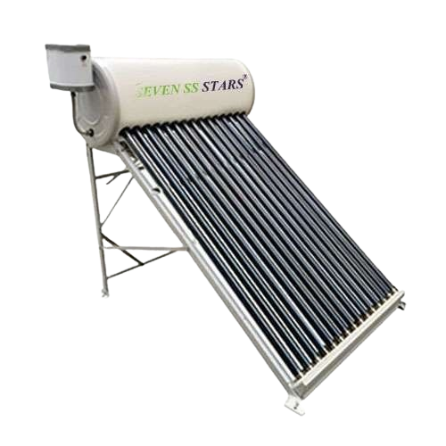
Non Pressurizable
Buy at SolarShop at the Best Price, support & Genuine warrany. Glean Energy is Now
- Solar Outdoor Lights
Best Deals on Genuine Manufacture's Official Brands Stores | SolarShop Africa
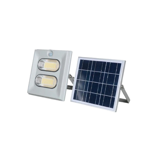
Solar Flood Lights

Solar Portable Lights

Solar Projects Lights
Buy at SolarShop at the Best Price, support & Genuine warrany. Glean Energy is Now
- Solar Water Pumps
Best Deals on Genuine Manufacture's Official Brands Stores | SolarShop Africa
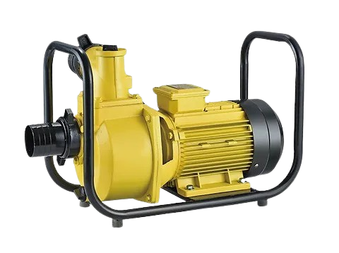
Irrigation Surface Solar DC Pumps
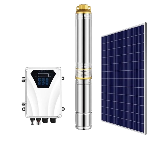
Submersible DC Solar Pumps & Controller
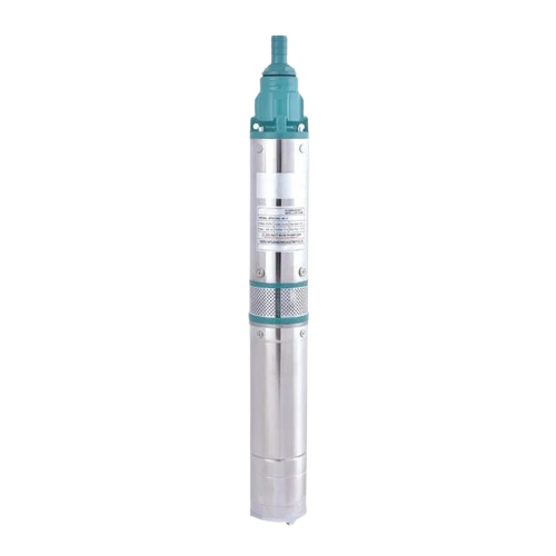
Submersible Solar DC Pump Controllerless
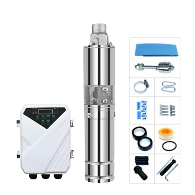
AC-DC Submersible Solar Pumps
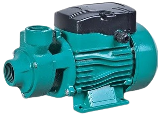
Solar Domestic Booster pumps
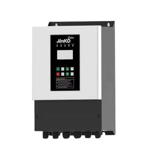
Hybrid Offgrid Pump Inverters
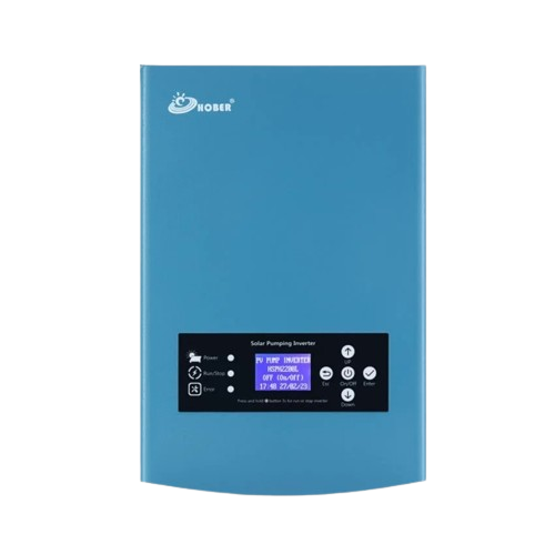
Hybrid Supplement Pump Inverters
Non-Supplement Pump Inverters

Budget Quality Pump Inverters

Premium Pump Inverters
Buy at SolarShop at the Best Price, support & Genuine warrany. Glean Energy is Now
Solarshop Africa Wholesale – Solar water Heaters, Inverters, Panels, and Batteries

Solar Water Heaters for Homes and Businesses
-
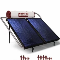
Eraslan 300 Liters Pressurized Flat Plate indirect Solar Water Heater
KSh350,000.00Original price was: KSh350,000.00.KSh295,000.00Current price is: KSh295,000.00. Add to cart -
Eraslan 200 Liters Pressurized Flat Plate indirect Solar Water Heater
KSh280,000.00Original price was: KSh280,000.00.KSh235,000.00Current price is: KSh235,000.00. Add to cart -
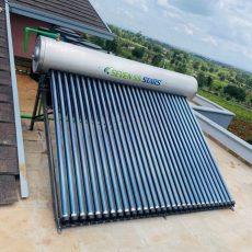
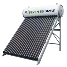
Seven SS Stars 250Liters Pressurized Heat-Pipe Tube Stainless Steel Solar Water Heater
KSh134,900.00 – KSh139,900.00Price range: KSh134,900.00 through KSh139,900.00 Select options -
Seven SS Stars 200 Liters Pressurized Heat-Pipe Tube Stainless Steel Solar Water Heater
KSh118,340.00 – KSh123,220.00Price range: KSh118,340.00 through KSh123,220.00 Select options -
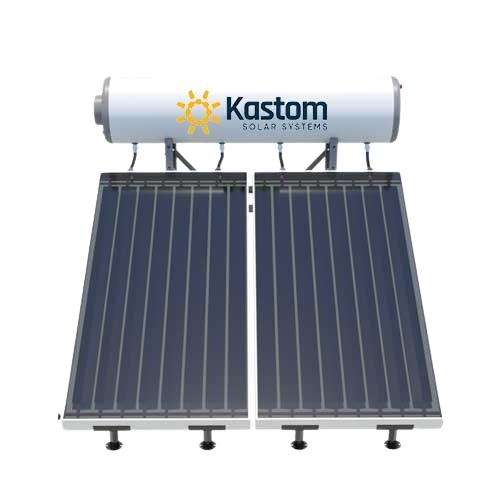
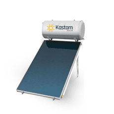
200 Liters Pressurized Flat Plate Indirect Premium Solar Water Heater | Kastom Solar
KSh240,000.00Original price was: KSh240,000.00.KSh185,000.00Current price is: KSh185,000.00. Add to cart -
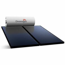
Chromagen 300 Liters Solar Water Heater Flat plate (closed loop) system
KSh390,000.00Original price was: KSh390,000.00.KSh350,000.00Current price is: KSh350,000.00. Add to cart -
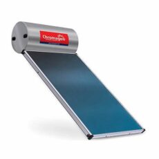
Chromagen 200 Liters Solar Water Heater Flat plate (Closed Loop) system
KSh290,000.00Original price was: KSh290,000.00.KSh250,000.00Current price is: KSh250,000.00. Add to cart -
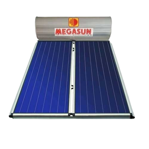
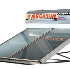
Megasun 300L Direct Flat Plate Pressurized Solar Water Heating System
KSh307,900.00Original price was: KSh307,900.00.KSh297,900.00Current price is: KSh297,900.00. Add to cart -
Megasun 200Liters Direct Flat Plate Pressurized Solar Water Heating System
KSh210,900.00Original price was: KSh210,900.00.KSh207,900.00Current price is: KSh207,900.00. Add to cart -
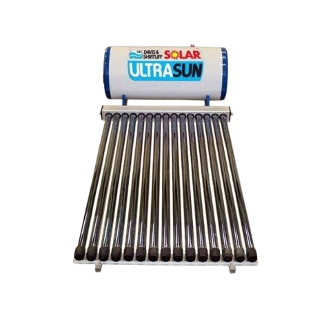
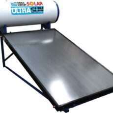
Ultrasun 200L Standard Flat plate Direct Solar Water Heater
KSh195,900.00Original price was: KSh195,900.00.KSh191,900.00Current price is: KSh191,900.00. Add to cart


Solar Inverters for Reliable Power Supply
-
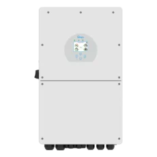
Deye 12 kW Hybrid Solar Inverter | Three phase Ongrid Low Voltage
KSh262,500.00Original price was: KSh262,500.00.KSh257,500.00Current price is: KSh257,500.00. Add to cart -
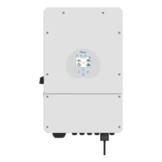
Deye 8 kW Hybrid Solar Inverter | Single phase Ongrid Low Voltage
KSh162,900.00Original price was: KSh162,900.00.KSh159,900.00Current price is: KSh159,900.00. Add to cart -
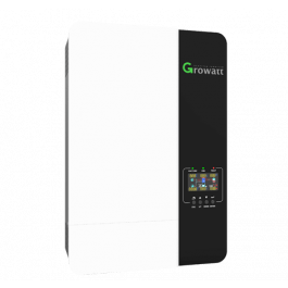
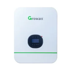
Growatt 3Kw Hybrid Solar Inverter 24V 80A SPF3000TL HVM
KSh65,000.00Original price was: KSh65,000.00.KSh59,000.00Current price is: KSh59,000.00. Add to cart -
Growatt 5KW Hybrid Solar Inverter 48V 80A SPF5000TL HVM
KSh99,000.00Original price was: KSh99,000.00.KSh89,000.00Current price is: KSh89,000.00. Add to cart -
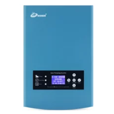
Hober 2.2Kw Solar Water Pumping Inverter | Single Phase
KSh58,000.00Original price was: KSh58,000.00.KSh55,000.00Current price is: KSh55,000.00. Add to cart -
Hober 5.5 kW Solar Water inverter | Hybrid Three Phase
KSh76,500.00Original price was: KSh76,500.00.KSh72,500.00Current price is: KSh72,500.00. Add to cart -
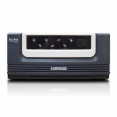
Luminous 1500 VA Ecovolt Inverter Charger | 24V
KSh22,900.00Original price was: KSh22,900.00.KSh20,800.00Current price is: KSh20,800.00. Add to cart -
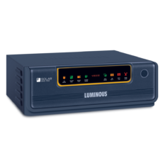
Luminous 850 VA NXG+ Hybrid Solar Inverter | 12V PWM
KSh22,500.00Original price was: KSh22,500.00.KSh18,500.00Current price is: KSh18,500.00. Add to cart -
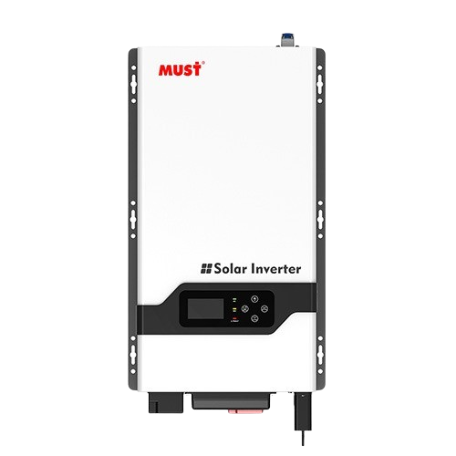
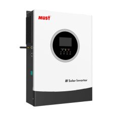
Must 3 kVA Hybrid Solar Inverter 24V | Low Frequency Offgrid VPM
KSh49,000.00Original price was: KSh49,000.00.KSh44,500.00Current price is: KSh44,500.00. Add to cart -
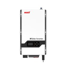
Must 5kVA Hybrid Solar Inverter 48V | Low Frequency Offgrid VPM
KSh71,300.00Original price was: KSh71,300.00.KSh64,500.00Current price is: KSh64,500.00. Add to cart -
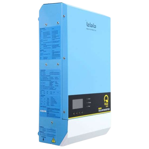
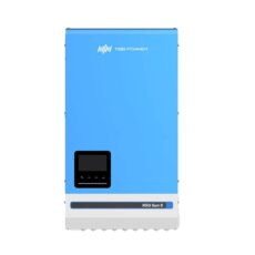
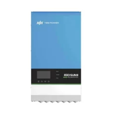
TBB Riio Sun II 8 kVA 48V Hybrid Solar Inverter & WiFi Dongle | Low Frequency
KSh162,900.00Original price was: KSh162,900.00.KSh158,500.00Current price is: KSh158,500.00. Add to cart -
TBB Riiosun II 3KVA | 24V Hybrid Offgrid Solar Inverter 150V/40A
KSh68,500.00Original price was: KSh68,500.00.KSh64,900.00Current price is: KSh64,900.00. Add to cart
-
Deye 125 kW Hybrid Solar Inverter | Three phase Ongrid High Voltage
KSh1,550,000.00Original price was: KSh1,550,000.00.KSh1,390,000.00Current price is: KSh1,390,000.00. Add to cart -
Deye 15Kw Three phase Ongrid | Grid Tied Duo MPPT Solar Inverter
KSh228,000.00Original price was: KSh228,000.00.KSh219,000.00Current price is: KSh219,000.00. Add to cart -
Deye 25Kw Three phase Ongrid | Grid Tied Duo MPPT Solar Inverter
KSh278,900.00Original price was: KSh278,900.00.KSh265,000.00Current price is: KSh265,000.00. Read more -
Deye 50 Kw Three Phase Ongrid Solar Inverter | Grid-Tied
KSh458,000.00Original price was: KSh458,000.00.KSh449,000.00Current price is: KSh449,000.00. Add to cart -
Deye 80 kW Hybrid Solar Inverter | Three phase Ongrid High Voltage
KSh1,200,000.00Original price was: KSh1,200,000.00.KSh980,000.00Current price is: KSh980,000.00. Add to cart -
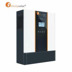
Felicity 5KVA | 48V Hybrid ongrid | Grid-Tie Solar Inverter | Single Phase
KSh149,900.00Original price was: KSh149,900.00.KSh137,500.00Current price is: KSh137,500.00. Add to cart -
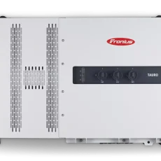
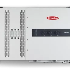
Fronius Eco 27.0-3-s Light 27 Kw 3 Phase Solar Inverter | Grid Tie
KSh505,000.00Original price was: KSh505,000.00.KSh495,000.00Current price is: KSh495,000.00. Add to cart -
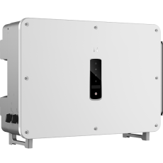
GoodWe 100 kW Ongrid Grid-Tied Solar Inverter
KSh580,000.00Original price was: KSh580,000.00.KSh555,000.00Current price is: KSh555,000.00. Add to cart -
GoodWe 125 kW Ongrid Grid-Tied Solar Inverter
KSh625,000.00Original price was: KSh625,000.00.KSh615,000.00Current price is: KSh615,000.00. Add to cart -
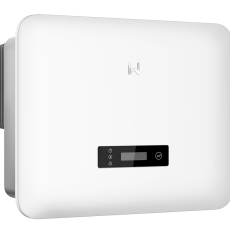
GoodWe 15 kW Ongrid Grid-Tied Solar Inverter
KSh165,000.00Original price was: KSh165,000.00.KSh155,000.00Current price is: KSh155,000.00. Add to cart -
GoodWe 25 kW Ongrid Grid-Tied Solar Inverter
KSh225,000.00Original price was: KSh225,000.00.KSh215,000.00Current price is: KSh215,000.00. Add to cart -
GoodWe 50 kW Ongrid Grid-Tied Solar Inverter
KSh350,000.00Original price was: KSh350,000.00.KSh320,000.00Current price is: KSh320,000.00. Add to cart

High-Efficiency Solar Panels in Wholesale Quantities
-
Africell 300W Monocrystalline Solar Panel
KSh12,900.00Original price was: KSh12,900.00.KSh10,900.00Current price is: KSh10,900.00. Add to cart -
Africell 350W Monocrystalline Solar Panel
KSh13,900.00Original price was: KSh13,900.00.KSh11,900.00Current price is: KSh11,900.00. Add to cart -
-
Amerisolar AS-6P30 – 280W Polycrystalline
KSh13,900.00Original price was: KSh13,900.00.KSh12,900.00Current price is: KSh12,900.00. Add to cart -
Felicity Solar 450W/40V monocrystalline half cell Solar panel | 1960x1060x35mm
KSh22,900.00Original price was: KSh22,900.00.KSh18,900.00Current price is: KSh18,900.00. Add to cart -
JA Solar 565 Watts Monocrystalline Solar Panel | Monofacial
KSh12,300.00Original price was: KSh12,300.00.KSh10,000.00Current price is: KSh10,000.00. Add to cart -
Jinko 620 Watts Monocrystalline Solar Panel | Bifacial
KSh12,900.00Original price was: KSh12,900.00.KSh11,400.00Current price is: KSh11,400.00. Add to cart -
-
Jinko Solar 550 Watts Monocrystalline Solar Panel
KSh12,900.00Original price was: KSh12,900.00.KSh10,400.00Current price is: KSh10,400.00. Add to cart -
Jinko Solar 580 Watts Monocrystalline Solar Panel
KSh11,400.00Original price was: KSh11,400.00.KSh10,600.00Current price is: KSh10,600.00. Add to cart -
RenePV 340 Watts ZY340P@W-72 Polycrystalline Solar Panel
KSh14,900.00Original price was: KSh14,900.00.KSh12,900.00Current price is: KSh12,900.00. Add to cart
-
340 Watts Monocrystalline Longi-Solar 72 Cell
KSh7,900.00Original price was: KSh7,900.00.KSh6,900.00Current price is: KSh6,900.00. Add to cart -
Africell 300W Monocrystalline Solar Panel
KSh12,900.00Original price was: KSh12,900.00.KSh10,900.00Current price is: KSh10,900.00. Add to cart -
Africell 350W Monocrystalline Solar Panel
KSh13,900.00Original price was: KSh13,900.00.KSh11,900.00Current price is: KSh11,900.00. Add to cart -
-
-
Amerisolar AS-5M-190W-Monocrystaline
KSh15,100.00Original price was: KSh15,100.00.KSh13,590.00Current price is: KSh13,590.00. Add to cart -
Dayliff 200W 43.5V monocrystalline solar
KSh10,800.00Original price was: KSh10,800.00.KSh8,600.00Current price is: KSh8,600.00. Add to cart -
Felicity 325w 36v Monocrystalline Solar Panel
KSh17,900.00Original price was: KSh17,900.00.KSh15,900.00Current price is: KSh15,900.00. Add to cart -
Felicity Solar 160w/18v monocrystalline solar panel | 1480x680x35mm
KSh8,500.00Original price was: KSh8,500.00.KSh7,900.00Current price is: KSh7,900.00. Add to cart -
Felicity Solar 260w/30v monocrystalline solar panel | 1640x992x35mm
KSh15,000.00Original price was: KSh15,000.00.KSh12,900.00Current price is: KSh12,900.00. Add to cart -
Felicity Solar 350w/30V monocrystalline half cell Solar panel | 1038x1580x35mm
KSh19,900.00Original price was: KSh19,900.00.KSh14,900.00Current price is: KSh14,900.00. Add to cart
-
200 Watts Topray polycrystalline Solar Panels
KSh12,900.00Original price was: KSh12,900.00.KSh11,500.00Current price is: KSh11,500.00. Add to cart -
-
-
-
Amerisolar AS-6P30 – 280W Polycrystalline
KSh13,900.00Original price was: KSh13,900.00.KSh12,900.00Current price is: KSh12,900.00. Add to cart -
-
JA 575W Bifacial solar panel
KSh12,900.00Original price was: KSh12,900.00.KSh10,200.00Current price is: KSh10,200.00. Add to cart -
RenePV 340 Watts ZY340P@W-72 Polycrystalline Solar Panel
KSh14,900.00Original price was: KSh14,900.00.KSh12,900.00Current price is: KSh12,900.00. Add to cart -
-
-
-
Jinko 615 Watts Bi-Facial Monocrystalline Solar Panel
KSh16,500.00Original price was: KSh16,500.00.KSh14,400.00Current price is: KSh14,400.00. Add to cart
-
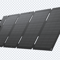
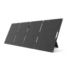
ECOFLOW FLEXIBLE SOLAR PANEL 100W
KSh16,000.00Original price was: KSh16,000.00.KSh14,900.00Current price is: KSh14,900.00. Add to cart -
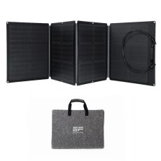
ECOFLOW PORTABLE SOLAR PANEL 110W (EFSOLAR110N)
KSh30,000.00Original price was: KSh30,000.00.KSh27,900.00Current price is: KSh27,900.00. Add to cart -
ECOFLOW PORTABLE SOLAR PANEL 160W (EFSOLAR160W)
KSh38,000.00Original price was: KSh38,000.00.KSh36,900.00Current price is: KSh36,900.00. Add to cart -
ECOFLOW PORTABLE SOLAR PANEL 220W (SOLAR220W)
KSh55,500.00Original price was: KSh55,500.00.KSh53,200.00Current price is: KSh53,200.00. Add to cart -
ECOFLOW PORTABLE SOLAR PANEL 400W (SOLAR400W)
KSh87,000.00Original price was: KSh87,000.00.KSh86,300.00Current price is: KSh86,300.00. Add to cart -
ECOFLOW PORTABLE SOLAR PANEL 60W (EFSOLAR60)
KSh17,000.00Original price was: KSh17,000.00.KSh15,190.00Current price is: KSh15,190.00. Add to cart -
ECOFLOW SOLAR PANEL 45W
KSh10,499.00Original price was: KSh10,499.00.KSh8,299.00Current price is: KSh8,299.00. Add to cart -
Hinen 100 Watts Portable Solar Panel
KSh22,900.00Original price was: KSh22,900.00.KSh18,900.00Current price is: KSh18,900.00. Add to cart -
Hinen 200 Watts Portable Solar Panel
KSh44,900.00Original price was: KSh44,900.00.KSh39,500.00Current price is: KSh39,500.00. Add to cart -
Hinen 2680 Wh PS2500B Expansion Lithium Battery for PS3000
KSh98,900.00Original price was: KSh98,900.00.KSh94,500.00Current price is: KSh94,500.00. Add to cart -
Hinen 400 Watts Portable Solar Panel
KSh70,900.00Original price was: KSh70,900.00.KSh67,500.00Current price is: KSh67,500.00. Add to cart -
Marstek Portable Solar Panel S200 200W
KSh45,000.00Original price was: KSh45,000.00.KSh37,900.00Current price is: KSh37,900.00. Add to cart
Long-Lasting Solar Batteries for Off-Grid and Backup Power
-
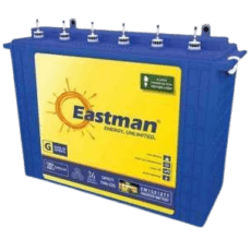
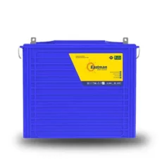
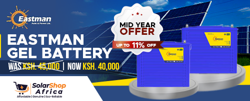
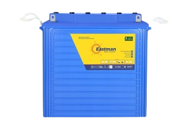
Eastman 220Ah 12V tubular flooded Battery
KSh34,500.00Original price was: KSh34,500.00.KSh26,900.00Current price is: KSh26,900.00. Add to cart -
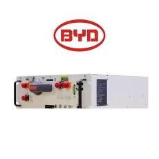
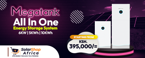
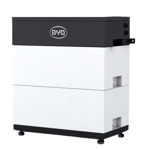
BYD 5KWh Lithium Solar Battery LV Flex Lite 5.0
KSh158,900.00Original price was: KSh158,900.00.KSh146,500.00Current price is: KSh146,500.00. Add to cart -
Felicity 5 kWh Lithium Battery | 24V 200Ah 6000 Cycles LPBF24200-M
KSh108,900.00Original price was: KSh108,900.00.KSh99,500.00Current price is: KSh99,500.00. Add to cart -
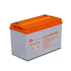
Felicity 100Ah Gel Battery | 12V Gel Maintenance Free Solar Battery
KSh19,900.00Original price was: KSh19,900.00.KSh16,900.00Current price is: KSh16,900.00. Add to cart -
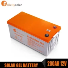
Felicity 200Ah Gel Battery | 12V Gel Maintenance Free Solar Battery
KSh36,000.00Original price was: KSh36,000.00.KSh32,900.00Current price is: KSh32,900.00. Add to cart -
Weco Lithium LFP Solar battery 5.3KWh/48V | 7000 Cycles
KSh399,900.00Original price was: KSh399,900.00.KSh379,900.00Current price is: KSh379,900.00. Add to cart -
-
-
Lithium valley 5Kwh Lithium Battery 48V Rack Mounted
KSh190,000.00Original price was: KSh190,000.00.KSh175,000.00Current price is: KSh175,000.00. Read more
-
-
-
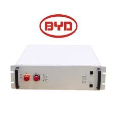
BYD 15.4 kWh Premium LVL Lithium Battery
KSh760,500.00Original price was: KSh760,500.00.KSh749,500.00Current price is: KSh749,500.00. Add to cart -
BYD 5kwh 48V LV 5.0 lithium ion battery box-LFP
KSh122,000.00Original price was: KSh122,000.00.KSh119,000.00Current price is: KSh119,000.00. Add to cart -
BYD 5KWh Lithium Solar Battery LV Flex Lite 5.0
KSh158,900.00Original price was: KSh158,900.00.KSh146,500.00Current price is: KSh146,500.00. Add to cart -
BYD 7.5 kWh Maxlite In Module HV Lithium Battery
KSh256,500.00Original price was: KSh256,500.00.KSh249,500.00Current price is: KSh249,500.00. Add to cart -
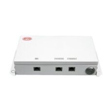
BYD Battery Monitoring Unit (BMU) for LV Flex Lite and Premium LVL Lithium Batteries
KSh29,900.00Original price was: KSh29,900.00.KSh22,900.00Current price is: KSh22,900.00. Add to cart -
BYD Levelling Feet for LV Flex Lite
KSh8,900.00Original price was: KSh8,900.00.KSh6,900.00Current price is: KSh6,900.00. Add to cart -
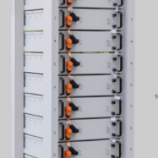
BYD Maxlite In Rack for 12 Units
KSh239,500.00Original price was: KSh239,500.00.KSh225,000.00Current price is: KSh225,000.00. Add to cart -
BYD Power Distribution Unit (PDU) Maxlite InPDU
KSh256,500.00Original price was: KSh256,500.00.KSh249,500.00Current price is: KSh249,500.00. Add to cart -
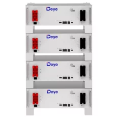
Deye 5.12 Kwh Lithium Battery 48V 100Ah | Low Voltage
KSh137,500.00Original price was: KSh137,500.00.KSh125,000.00Current price is: KSh125,000.00. Add to cart
-
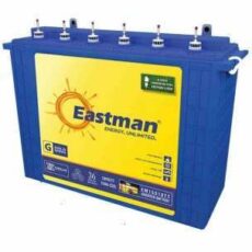
Eastman 200Ah 12V Tall Tubular Deep Cycle GEL Battery
KSh42,900.00Original price was: KSh42,900.00.KSh35,500.00Current price is: KSh35,500.00. Add to cart -
Eastman 220Ah 12V tubular flooded Battery
KSh34,500.00Original price was: KSh34,500.00.KSh26,900.00Current price is: KSh26,900.00. Add to cart -
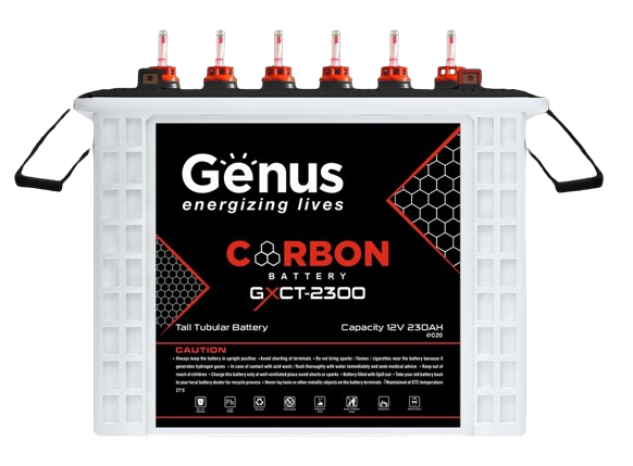
Eastman 300Ah 12V Tall Tubular Deep Cycle Battery
KSh59,900.00Original price was: KSh59,900.00.KSh52,900.00Current price is: KSh52,900.00. Add to cart -
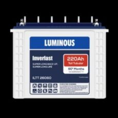
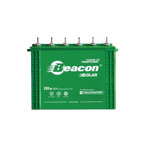
Luminous 220 Ah Tubular Solar Battery | 12V Volt ILTTEX150
KSh39,900.00Original price was: KSh39,900.00.KSh36,200.00Current price is: KSh36,200.00. Add to cart
-
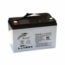
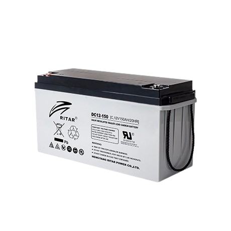
100Ah/12v Ritar Power Maintenance Free Battery
KSh27,000.00Original price was: KSh27,000.00.KSh24,900.00Current price is: KSh24,900.00. Add to cart -
200Ah/12v Ritar GEL Power Maintenance Free Battery
KSh44,900.00Original price was: KSh44,900.00.KSh42,900.00Current price is: KSh42,900.00. Read more -
-
-
-
-
-
Felicity 100Ah Gel Battery | 12V Gel Maintenance Free Solar Battery
KSh19,900.00Original price was: KSh19,900.00.KSh16,900.00Current price is: KSh16,900.00. Add to cart -
Felicity 150Ah Gel Battery | 12V Gel Maintenance Free Solar Battery
KSh29,900.00Original price was: KSh29,900.00.KSh23,900.00Current price is: KSh23,900.00. Add to cart -
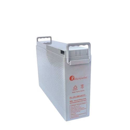
Felicity 200Ah Gel Battery | 12V Gel Maintenance Free Solar Battery
KSh36,000.00Original price was: KSh36,000.00.KSh32,900.00Current price is: KSh32,900.00. Add to cart

Solar Garden Lights, Street Lights, and Gate Lights
-
-
-
-
-
-
-
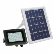
AllTop 50Watts Solar Flood Lights
KSh3,200.00Original price was: KSh3,200.00.KSh2,800.00Current price is: KSh2,800.00. Add to cart -
-
-
-
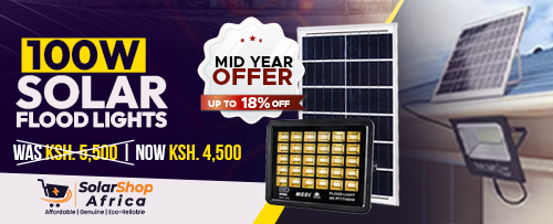
MODI 100 Watts LED Solar Flood Light MD-PT77 Series
KSh5,500.00Original price was: KSh5,500.00.KSh4,500.00Current price is: KSh4,500.00. Add to cart
-
-
-
-
-
-
-
-
-
Felicity Solar 80Watts All in Two Solar Street Light | Metallic
KSh34,900.00Original price was: KSh34,900.00.KSh28,900.00Current price is: KSh28,900.00. Add to cart -
Felicity Solar 60Watts All in Two Solar Street Light | Metallic
KSh24,900.00Original price was: KSh24,900.00.KSh20,900.00Current price is: KSh20,900.00. Add to cart -
Felicity Solar 60Watts All in One Solar Street Light | Metallic
KSh42,900.00Original price was: KSh42,900.00.KSh37,900.00Current price is: KSh37,900.00. Add to cart -
Felicity Solar 40Watts All in Two Solar Street Light | Metallic
KSh20,900.00Original price was: KSh20,900.00.KSh16,900.00Current price is: KSh16,900.00. Add to cart
-
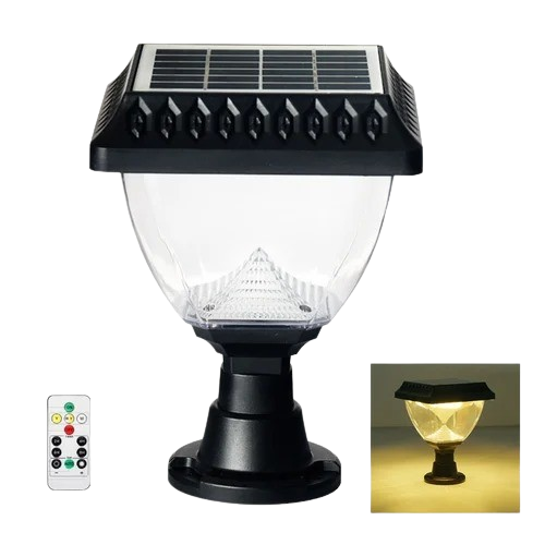
Kastom Solar Garden Lights KE-802 L
KSh8,745.00Original price was: KSh8,745.00.KSh7,950.00Current price is: KSh7,950.00. Add to cart -
Kastom Solar Garden Lights KE S
KSh6,000.00Original price was: KSh6,000.00.KSh5,450.00Current price is: KSh5,450.00. Add to cart -
-
-
Kastom Solar Garden Lights KE-803 S
KSh5,500.00Original price was: KSh5,500.00.KSh5,450.00Current price is: KSh5,450.00. Add to cart -
Kastom Solar Garden Lights KE-806 L
KSh7,000.00Original price was: KSh7,000.00.KSh6,450.00Current price is: KSh6,450.00. Add to cart -
-
-
-
Kastom Solar Garden Lights KE-807 S
KSh4,400.00Original price was: KSh4,400.00.KSh3,950.00Current price is: KSh3,950.00. Add to cart -
-
Solar Water Heaters
At SolarShop Africa, we supply a wide range of solar water heaters from leading global and local brands, including
Seven SS Stars,
Agrosol Solar,
Eraslan,
Kastom Solar,
Megasun,
Supreme Solar,
Ultrasun Solar, and
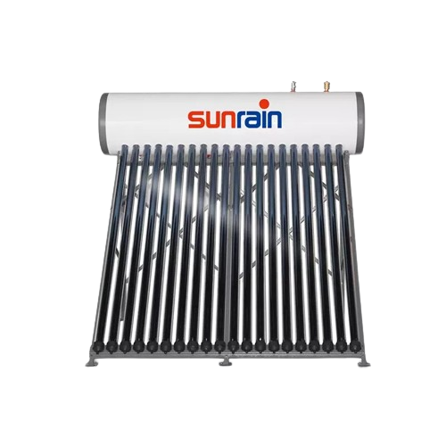
Sunrain Solar. Our bulk prices are designed to give you maximum value, making us the preferred supplier for contractors, hotels, apartments, institutions, and resellers across Kenya and East Africa.
Whether you need pressurized, non-pressurized, split systems, or commercial-grade solutions, our range is tested for durability, energy efficiency, and performance in all climates. We handle both residential and large-scale commercial projects, offering competitive discounts for bulk orders and reliable nationwide delivery. By partnering with trusted brands, we guarantee you receive solar water heating systems that meet KEBS quality standards and deliver long-term savings. With SolarShop Africa, buyers benefit from expert guidance, authentic products, and after-sales support to keep your business running smoothly.
Solar Inverters
Our solar inverters range includes top-performing brands like
Jinko,
Veichi, and
Vestwoods. These inverters are engineered for reliability, high conversion efficiency, and compatibility with both on-grid and off-grid solar systems, ensuring optimal performance for your projects.
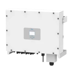
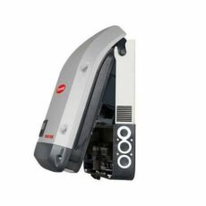
We supply hybrid, string, and central inverters in bulk quantities for residential, industrial, and commercial applications. Our pricing is tailored to help installers, resellers, and EPC contractors maximize profitability without compromising on quality. Each inverter is sourced directly from the manufacturer, ensuring warranty coverage and compliance with international and Kenyan energy standards. From small-scale setups to multi-megawatt installations, we have the right inverter solutions to keep your clients powered efficiently.
Solar Lights
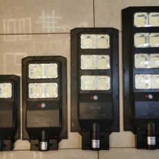
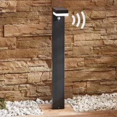
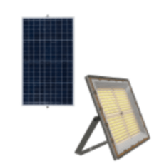
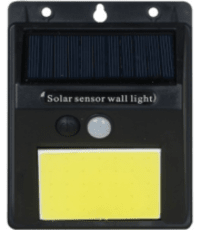
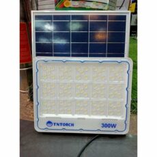
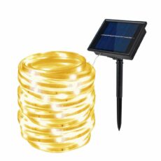
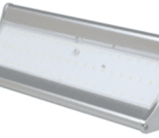
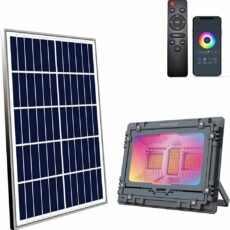
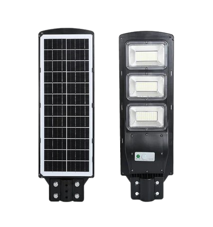
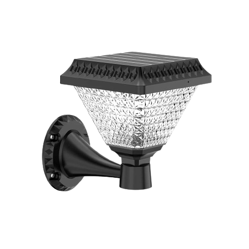
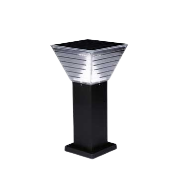
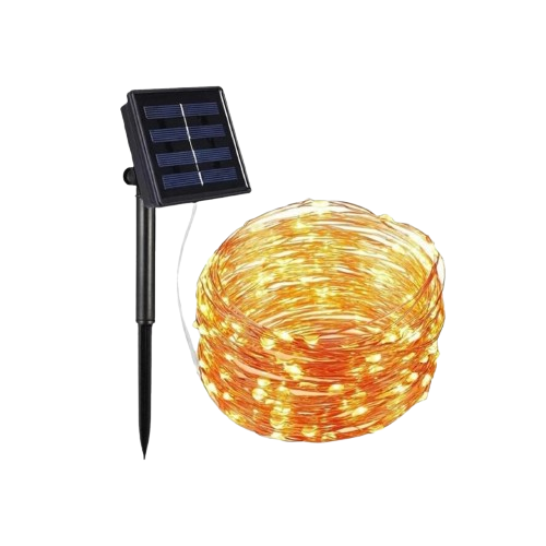
Our solar lights are available for municipalities, construction companies, real estate developers, and retailers looking for durable, high-output lighting solutions. We stock solar street lights, flood lights, garden lights, and motion-sensor security lights designed for long life and low maintenance.
By purchasing from us, you benefit from competitive rates, diverse products, and fast delivery. All our solar lights are built to withstand harsh weather while delivering consistent illumination. We also offer customizable solutions for large-scale lighting projects, ensuring energy efficiency and reduced operational costs for years to come. Our lights are ideal for both private and public sector installations, enhancing safety and sustainability.
Solar Panels
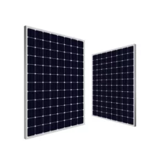
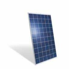
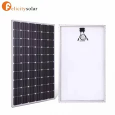
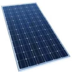
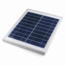
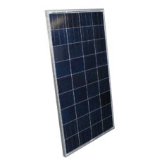
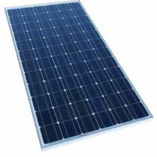
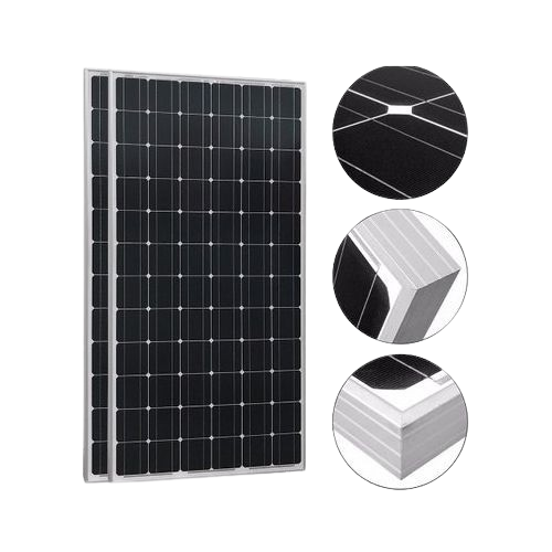
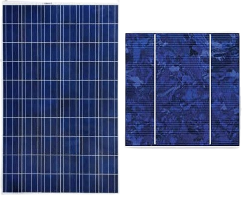
SolarShop Africa is a trusted supplier of solar panels for small to large-scale installations. We source high-efficiency monocrystalline and polycrystalline panels from leading manufacturers, offering power ratings suitable for residential, industrial, and commercial applications.
Our bulk supply chain ensures cost-effective pricing for installers, contractors, and government projects. With a focus on durability, performance, and long-term energy savings, our panels come with manufacturer warranties and quality certifications. We provide expert guidance on selecting the right panel wattage and quantity to match your project requirements. Whether for a residential rooftop or a large commercial development, we have the right panels to meet your energy goals.
Solar Batteries
We supply a wide selection of solar batteries including lithium-ion, gel, and deep cycle models. Our brands are known for exceptional storage capacity, long cycle life, and dependable performance in both off-grid and backup systems.
Whether you are powering homes, offices, or large-scale industrial facilities, our pricing helps you scale profitably while offering clients the best in energy storage technology. All batteries are sourced from trusted brands, tested for quality, and delivered promptly to your location anywhere in Kenya. These batteries are perfect for renewable energy projects, providing consistent energy during peak hours or power outages.
Order from SolarShop Africa for reliable solar products. Learn more about solar energy from the International Energy Agency.












-31-230x230.png)
